Wednesday, 7 November 2012

The primed m.g. mounding. 
Another view. 
Here you can see the m.g. splash guard already sand blasted, this component prevents any bullets that happen to squeeze through the gaps from injuring the crew. 
Another view of the shield. 
And primed waiting for the interior colour. 
One of the turrets side pistol ports being stripped. 
The rotation plate which is relatively free of any contact surface rust, the thick layers of paint are to thank for this. 
Not so with the outer exposed armoured swivel plate. 
The swivel retention plate from the inside. 
This part should have been stripped before the major sandblasting was carried out as can be seen in the surrounding area.

The gimbal mounting ring has been sandblasted. 
This view shows the hard wearing layer of baked on black enamel, even sandblasting hasn't been able to remove the coating. 
All the mg components after sandblasting. 
A close up view of some of the parts, the two discs in the middle are the elevation/depression bearings. 
The armoured shield. 
Looking into the housing after some sandblasting has taken place.
Once again everything was re assembled to have a look how it all fits together and make sure some smaller items haven't slipped through the sandblasting grid. 
Looking into the housing once again. Note that the upper and lower rotation bearings are externally mounted and that the elevation/depression bearings are located on the inner surface. 
A side view. 
The top view, the upper and lower bearings attach the mounting to the armoured car. 
Right hand side view.

The turret rear access hatch, you can see the layers of paint and traces of the various colours that have been applied over the years. 
Some light sandblasting to loosten up the bolts and then the mechanism was removed. 
Here it has all been sandblasted 
This is how the mechanism works. 
A picture out of sequence that shows the stripped down components of the turret mounted periscope. 
The components of the hull machine gun mounting.  
An underside view of the gun locking frame. 
A side view showing the original baked on black enamel colour. 
Looking into the mounting, the tube is for the sighting telescope and the oval slot to accommodate the gun barrel. 
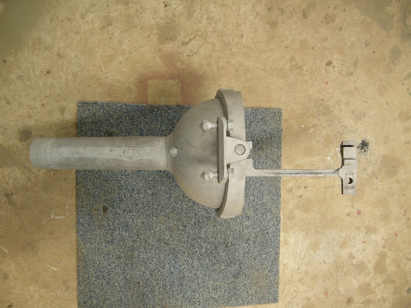
The outer pivoting ring or gimbal mounting. 
And here is the armoured ball that protects everything.

Tuesday, 6 November 2012

Attention was now turned to the periscope mounting bracket that is located inside the turret roof. Here you can see the item already sandblasted.  
A detailed view. 
From another angle. The centre piece slides between the outer rails in a gentle arc, this allows the head of the periscope to be tilted and view various angles. The knurled locking nut can be seen protruding downwards.
Another bit added. 
This is the rough orientation of how it sits inside the exterior bulbous armoured shield. 
I temporarily bolted it to the upturned turret roof to show how it is mounted. 
From this side one can see the swivelling locking nut, you can also see the path of the curved arc. 
The two above photos shows the full swing of the mounting. 
In this closeup the curved groove is clearly seen.
Another view of it mounted inside the turret.

Friday, 2 November 2012

Here is the turret traverse mechanism, the handle is Bakelite. 
And another view. 
After some stripping to check out the workings and condition of the components. 
The worm gear. 
The main gear. 
After sandblasting it all looks nice and clean. 
Beautiful bit of engineering. 
Assembled and undercoated. 
The top view, the two exposed gears are really like that, no cover or protection whatsoever. 

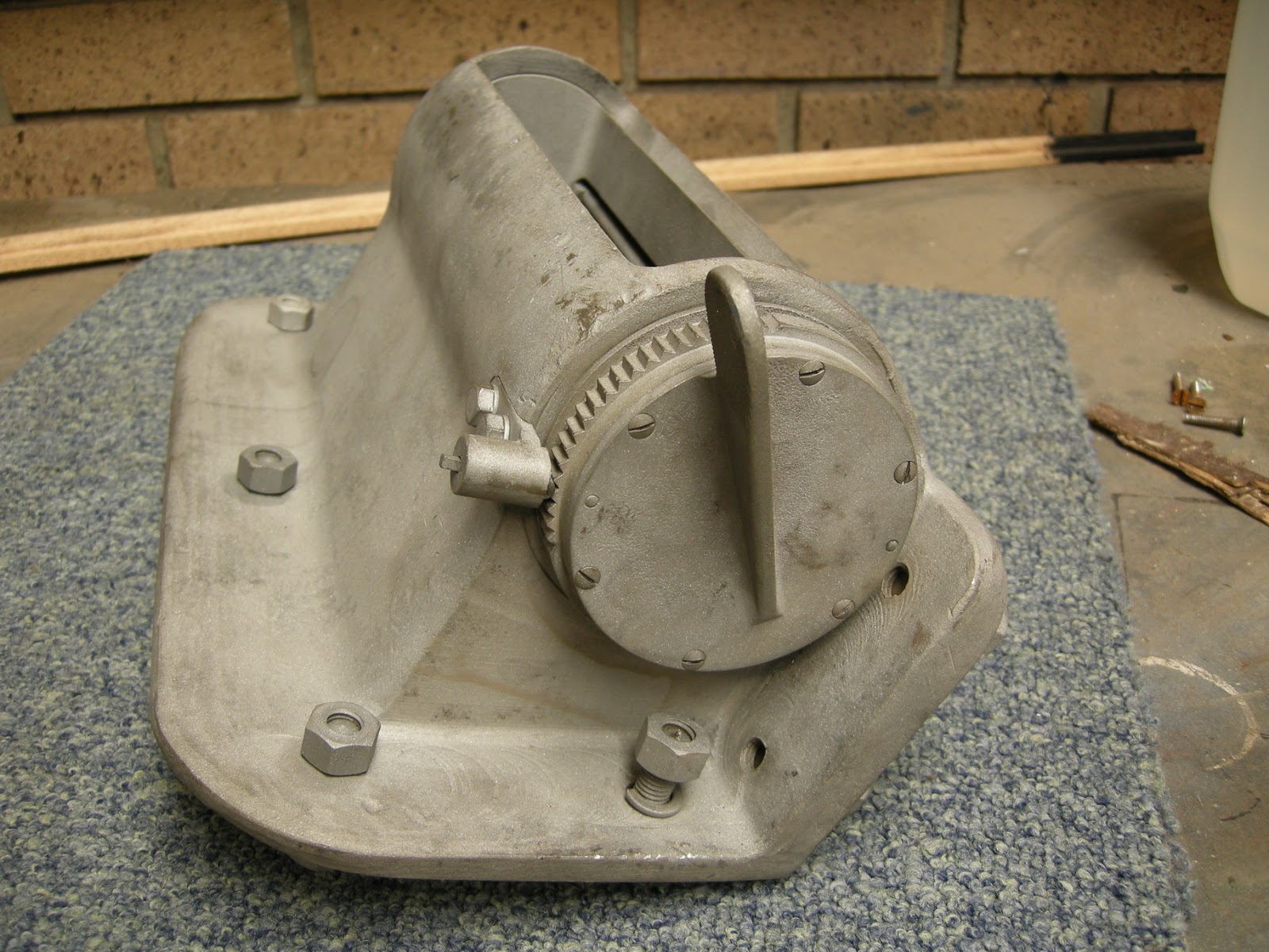
With the periscope mounting sandblasted and all clean it was assembled to see how it all works. 
This portion is exposed on the armoured car. With the periscope removed the circular inner tube can be rotated and closed off. 
The serrations and spring loaded plunger that locks the inner tube in various positions, it is rotated via the thumb latch seen on the right.  
Looking into the housing one can see the periscope retention catch, in this position the periscope can be inserted into the housing.  
And here you can see the catch rotated, in this position the periscope would be locked in place. 
A left hand side view, the thumb latch seen on this end is for locking the periscope in place. 
The right hand side showing the details.