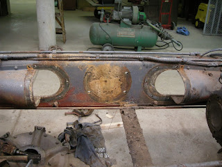
With the transfer box out of the way one can see the attatchment from the gearbox.
Another view.
Looking to one inner side of the chassis we can see the mounting location for the transfer box.
After careful removal of any attachments the gearbox is separated and lifted out.
The input shaft with thrust bearing.
An overall view showing the gearbox removal.
A close up of the input shaft and thrust bearing, the braided pipe is the lubrication pipe for the thrust bearing.
Here the pressure and clutch plate can be seen.
Lifting out the gearbox.
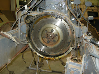
In the bell housing the flywheel is visible.


No comments:
Post a Comment