The following images are of the aluminium spacer plate for the suspension.
The six suspension mounting bolts.
Two bolts from the inside of the chassis. You can see the shape of the inner casting.
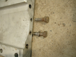
Two more mounting bolts on the lower girder of the chassis frame.
Some more interesting stampings recorded for posterity.
This is the front view, the spring sits in the recess.
Primed spacer plates.
Another view.
And painted in the correct colour.
Now that the suspension units and various components have been primed and painted the parts are laid out for assembly.
The engine jack comes in handy for this task, no point in pulling a muscle or causing a hernia.
One suspension unit in place, you can see how the spacer bracket takes up the space between the girder and the unit.
Another angled view, the two rotary type shock absorbers can bee seen on either side of the the upper wishbone.
All those nuts and bolts lock the whole suspension bracket and various components in place.
A lower side view, you can see how the shock absorbers are mounted to the side of the chassis.


No comments:
Post a Comment